
If you are evaluatingoptical inspection systems for precision parts, the hardest decision is rarely the camera. It is deciding what the system is supposed to prove.
An optical inspection system uses controlled light, optics, a camera and image-processing software to examine a manufactured part without touching it. Depending on the configuration, it can flag a missing feature, compare a silhouette against a drawing, or return a calibrated dimension in microns. Those are three different jobs with three different acceptance criteria — and treating them as one is the most common reason a vision project fails its acceptance test.
Automated optical inspection (AOI) answers“Is this part good?”.Vision metrology answers“What is the value, and how much can I trust it?”. This guide walks QC engineers through the categories of optical inspection equipment, the features that matter for stamped, molded, PCB and sealing parts, the three lighting geometries that decide what you can actually see, and the trade-off between batch throughput and precision measurement. At the end you will find a deployment checklist, an FAQ, and a way to validate the whole framework on your own parts for free.
If you already have parts on the bench, you can jump to the sample test at the end — but the framework below will tell you what to ask for.
1. What Are Optical Inspection Systems? Definition and Categories
Takeaway: Inspection tells you whether a part passes. Metrology tells you how far it is from nominal — and whether the number is trustworthy.
Optical inspection is a family of non-contact techniques that examine component geometry, measure visible features and identify surface defects using light-based imaging. It is used across precision machining, injection molding, electronics, sheet metal and prototype development. The term covers several technologies that are not interchangeable. A conventional inspection camera may detect a missing hole; a calibrated vision measuring machine reports its diameter. Some platforms do both, but their acceptance criteria should be defined separately.
| System category | What it returns | Best fit | Watch-out |
|---|---|---|---|
| Optical comparator (profile projector) | Magnified 2D silhouette for overlay or visual comparison | Flat stamped profiles, radii, angles, gear teeth | Planar geometry only; no Z-axis data; operator-dependent |
| Automated optical inspection (AOI) | Pass/fail plus defect classification | Component presence and polarity, assembly verification, code and label reading, surface defect scanning | Detection performance must be validated with representative goodanddefective parts |
| Vision measuring machine (VMM) / one-shot flash system | Absolute dimensional values with a report | Hole diameters, centre distances, slot widths, radii, 2D profiles of small parts | Capability depends on calibration, optics, field of view, datum alignment and the measurement program |
| Hybrid / 3D systems (laser, confocal, structured light, vision probe on CMM, CT) | Height, flatness, volume, hidden geometry | Deep bores, warpage, full 3D GD&T, roughness | Slower and costlier; some are sensitive to reflective or shiny surfaces |
Notice the verbs:detect, compare, measure. Confusing them is expensive in an RFQ. Ask a supplier for AOI and you will be quoted a system optimized for speed; ask for a vision measuring machine and you will be quoted one optimized for accuracy. If your acceptance test demands a value at ±5 µm, write the requiredoutputinto the specification — not just the technology name.
One-shot (often called “flash”) measurement belongs in the third row: a double-telecentric lens captures the whole part in a single field of view, and the software extracts every programmed dimension at once, with parts placed anywhere in the field. It is fast precisely because it does not move a stage — which also defines where it stops being the right tool.
2. Optical Inspection for Precision Parts: What to Check, Part by Part
Takeaway: The part’s material and failure mode decide the lighting; the drawing decides the measurement program.
| Part type | Critical features | Recommended illumination | Typical pitfall |
|---|---|---|---|
| Stamped / sheet metal | Perimeter profile, hole position, slot width, burrs, cut-edge quality | Backlight silhouette; low-angle ring for burrs | Reflective sheared edges and burrs can pull edge detection off by a few pixels |
| Injection-molded plastic | Short shots, flash, sink marks, openings, connector features, warpage | Diffuse ring / dome light; backlight for transparent parts | Contact probes deform flexible or thin-wall parts; shrinkage, moisture and temperature shift results |
| PCB / electronics | Solder joints, component presence and polarity, solder balls, silk screen, lifted leads, foreign material | High-angle diffuse ring brightfield; low-angle darkfield for scratches | Marginal solder joints and subtle wetting differences drive false calls on rule-based AOI |
| O-rings / seals | Inner diameter, outer diameter, wall thickness, concentricity, nicks, missing material | Parallel (telecentric) backlight silhouette; diffuse ring for surface defects | Hard fixtures distort soft rubber; glossy patches create local glare |
Stamped parts. Flat profiles, cutouts and hole locations are the natural territory of optical inspection, because backlighting produces a crisp silhouette. Validate with samples that actually have burrs — a program tuned only on clean edges will behave differently on the production line.
Molded parts. Non-contact measurement is not a luxury here: a caliper or touch probe can deform the very feature you are trying to check. Interpret results alongside material shrinkage, conditioning and ambient temperature, and be cautious with transparent or semi-crystalline parts.
PCBs. This is the home turf ofautomated optical inspection. Rule-based AOI performs extremely well when defect boundaries are crisp, lighting is stable, and the defect list is a finite set of presence/absence or threshold checks — component presence, polarity, date codes, pin protrusion. It struggles when the difference between an acceptable and a marginal joint is subtle and shifts with solder paste lots or the reflow profile. Define those cases explicitly in the validation sample set.
Seals. Inner and outer diameter, wall thickness and concentricity fall out cleanly from a parallel-backlight silhouette; surface nicks need soft diffuse illumination instead. A dedicated seal routine that returns all core dimensions without programming is worth more than a generic edge tool you have to re-teach for every size.
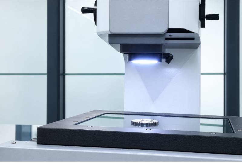
3. Lighting Selection: Backlight, Coaxial and Ring Light
Takeaway: Most field debugging time goes into illumination, not camera selection — light decides which features exist in the image at all.
Backlight / telecentric parallel backlight
A backlight sits behind the part: the camera sees a bright, uniform field with a black silhouette. Edge contrast is excellent, which makes it the default for dimensional work — outer diameters, through-holes, slot widths, O-ring ID/OD. Aparallel(telecentric) backlight keeps the apparent edge position stable even when the part sits slightly high or low. What it cannot show: scratches, colour, texture. If your defect list is surface-based, backlight alone will hide it.
Coaxial light
A 45° beamsplitter injects light down the lens axis. On a flat, mirror-like surface the specular reflection returns straight into the camera, while scratches, particles, dents and pressed characters scatter light and appear bright. It is the go-to for polished metal, glass cover plates, wafers and etched codes. The trade-off: the beamsplitter costs more than half the available light, so plan for a high-brightness source and independent intensity control.
Ring light
LEDs arranged around the lens, with the camera looking through the centre.High-angle / diffuse brightfield suits solder joints, marking OCR and general appearance.Low-angle darkfield turns tiny height differences into shadows, popping out scratches, burrs and foreign particles. Adiffuse, dome-style ring tames glare on curved or semi-gloss rubber. Watch for the ring’s own reflection appearing on mirror surfaces — add a diffuser.
Figure 1 — Same part, three lighting geometries. Three panels showing one perforated metal part with a fine scratch and an edge burr: (A) backlight producing a high-contrast silhouette with the scratch invisible; (B) coaxial light making the scratch bright against a dark flat surface; (C) ring light in low-angle darkfield revealing the burr as a shadow.
Colour is a contrast tool, not decoration. Blue light scatters strongly off fine scratches on metal; red transmits through many plastics; infrared ignores visible ambient flicker and can see through certain coatings. If one part number needs both a silhouette and a surface check, switching wavelength or channel is often cheaper than adding a second station.
This is why a serious system offers several channels rather than one “best” light: programmable surface ring, telecentric backlight and coaxial illumination, each with its own intensity level, let you validate and save a lighting recipe per part number instead of rebuilding a fixture every time the surface finish changes.
4. Batch Speed vs. Precision Measurement
Takeaway: Fast and accurate are not two grades of the same machine. They are two different acceptance logics.
Here is the trade-off most datasheets blur. AOI has to be fast, so it uses a large field of view at low magnification. Raise magnification for accuracy and the field shrinks, depth of field gets shallow, and stitching several images introduces error. Worse, high-accuracy dimensional work often needs to align the part to a datum that liesoutsidethe current field of view — beyond the reach of a typical in-line AOI. Stitching is a workaround, not a free upgrade.
| High-speed batch inspection | Precision dimensional measurement | |
|---|---|---|
| Output | OK/NG, defect count, sort signal | Absolute values, report, stated uncertainty |
| Optics | Large-field double-telecentric, single capture | Higher-magnification zoom, smaller field, staged moves |
| Part handling | Arbitrary placement, automatic feature recognition, multiple parts per capture | Datum alignment, repeatable positioning, programmed routine |
| Validation | Good/bad sample library, false-accept and false-reject rates | Calibration traceability, gauge R&R (MSA), temperature compensation |
| Data | Counts, yield, sorting | SPC charts, MES upload, barcode-linked reports |
| Question answered | “Do I ship this part?” | “Is my process drifting, and by how much?” |
Resolution is not accuracy. Pixel pitch is the width of the finest tick on the ruler; measurement uncertainty also includes calibration traceability, lens distortion, perspective, thermal expansion and operator-independent edge detection. On steel parts in an uncontrolled shop, thermal expansion alone can dominate the error budget. So validate with an MSA onyourparts, across multiple operators and repeated placements — not with a number from a brochure.
A three-question decision tree
- Only OK/NG, high volume? → AOI or one-shot flash inspection. Optimize the lighting and the defect sample library, not the magnification.
- Need numbers against a drawing, with reports? → A vision measuring machine. Optimize calibration, datums and uncertainty.
- Part larger than a single field of view, or both requirements at once? → Dual optics with a movable stage and stitching; add confocal, laser or touch sensors for height, depth and flatness.
Figure 2 — Decision tree.
Choose optical inspection systems by required output: OK/NG leads to AOI or one-shot flash measurement; dimensional values lead to a vision measuring machine; both plus a large part lead to dual-vision movable-platform stitching.
Where our three configurations fit
- K100 — fixed-platform one-shot flash measurement. Place small flat or rod-shaped parts anywhere in the field, press once, and get every programmed dimension. Multiple identical parts can be measured in the same capture, and a dedicated O-ring routine returns inner diameter, outer diameter and wall thickness with no programming. This is the answer when the question is“How many parts per hour, with no fixture and no trained operator?”
- K-Series Movable — one-shot workflow on a servo-driven XYZ stage. Stitching extends the effective measuring range beyond a fixed platform, so larger parts and multi-feature programs stay in one automated run. The open Z-axis also leaves room for robot loading. This is the answer when a part simply will not fit in one field of view.
- K433 — the dual-vision configuration. A large-field telecentric lens covers the whole part quickly; a high-magnification zoom lens handles micron-level measurement of small features, switchable inside one program. Independent surface, contour/back and coaxial lighting channels handle dark, reflective and complex surfaces, and optional confocal, laser or touch sensors add height, depth and flatness. This is the answer when you would otherwise buy two machines.
Whichever route you take, put the acceptance test in writing before the purchase order: which dimensions, which tolerance, which gauge R&R target, which sample set, which temperature range.
5. Implementation: Six Steps and the Pitfalls That Actually Happen
Takeaway: A vision project is validated on parts and procedures, not on a specification sheet.
- Freeze the drawing revision and select the dimensions that affect fit, function and downstream assembly. Not every dimension needs to be measured.
- Build a sample library: good parts from across the tolerance band, plus known defects — a burr, a short shot, a lifted lead, a nicked seal.
- Validate lighting first, using production-representative surface finish, and save the recipe per part number.
- Define datums and the measurement program. Decide whether arbitrary placement is acceptable or a fixture is genuinely needed.
- Calibrate, then run an MSA / gauge R&R with multiple operators and repeated placements; add temperature compensation if the shop is not controlled.
- Connect the output: report format, barcode linkage, SPC control charts, MES upload and a scheduled re-verification.
| Symptom | Likely cause | Fix |
|---|---|---|
| Spec sheet looks excellent; first articles disagree with the CMM | Resolution quoted as accuracy; no traceable calibration or datum alignment | Run an MSA on your parts against a calibrated reference |
| Random false rejects after a shift change | Ambient light drift, unlocked intensity, part temperature | Enclosure, locked lighting recipe, temperature compensation |
| Defects keep escaping | Program validated only on good parts | Add known-bad samples and measure the false-accept rate |
| Large-part measurements drift near the edges | Stitching without a unified coordinate system | One datum for all tiles; verify overlap regions |
| Soft parts measure differently every time | Contact probe or rigid fixture deforms the part | Non-contact optics with arbitrary placement |
| Reports exist but nobody acts on them | PDF-only output | SPC / MES integration with control charts |
Pre-Deployment Checklist
- [01 ] Drawing revision frozen; critical dimensions marked with tolerances
- [02 ] Good parts spanning the tolerance band + known defective parts available
- [03 ] Lighting recipe tested on the real surface finish and saved
- [04 ] Datums and part-placement strategy documented
- [05 ] Calibration certificate and traceability on file
- [06 ] Gauge R&R target agreed and measured
- [07 ] Report, barcode, SPC and MES interfaces defined
- [08 ] Re-verification interval and owner assigned
6. FAQ
What is an optical inspection system?
A non-contact setup combining controlled illumination, lenses, an industrial camera and image-processing software to examine a manufactured part. Depending on the configuration, optical inspection systems can detect visible defects, verify a profile, or measure dimensions such as hole diameters, centre distances, widths, radii and angles. Visual inspection and optical dimensional metrology are different jobs with different acceptance criteria.
What is the difference between automated optical inspection (AOI) and a vision measuring machine?
AOI uses image processing to find predefined defects or confirm assembly conditions and returns a pass/fail decision — its priority is speed and correct classification. A vision measuring machine returns absolute dimensional values with a report, and its priority is accuracy with a defined measurement method and uncertainty. Some systems do both, but validate each capability separately. If your RFQ says “inspection” while your acceptance test asks for ±5 µm, rewrite the RFQ.
Can one system handle both high-speed batch checks and micron-level measurement?
Yes, with dual optics: a large field for whole-part coverage, a high-magnification lens for small features, and a movable stage with stitching for parts larger than one field of view. The important part is procedural — run separate programs and separate acceptance criteria for the OK/NG check and for the dimensional report.
Which light should I use for optical inspection for precision parts such as O-rings, stamped metal and PCBs?
Use a parallel backlight for O-ring ID/OD and wall thickness, and for stamped-part silhouettes and hole positions. Use low-angle ring darkfield to expose burrs and fine scratches on metal. Use high-angle diffuse ring light for PCB solder joints, silk screen and marking OCR, and coaxial light for fine scratches on flat reflective or glass surfaces. Most real programs combine two or three channels.
How do I validate measurement accuracy — and why isn’t camera resolution enough?
Run a gauge R&R (MSA) with multiple operators, repeated placements and parts spanning the tolerance band, against a calibrated reference. Resolution describes the finest detectable increment; uncertainty also includes calibration traceability, lens distortion, perspective, thermal expansion and edge-detection repeatability. A high pixel count without calibration and stability is expensive noise.
What can’t 2D optical inspection measure?
Deep bores, hidden or internal features, full 3D GD&T such as true position on complex geometry, and surface roughness. For those, add a confocal or laser displacement sensor, a touch probe, a vision-equipped CMM or CT — and confirm the surface finish is compatible with the sensor.
How should I prepare for a free sample test?
Send 3–5 good parts spanning the tolerance band, 2–3 known defective parts, the drawing with critical tolerances marked, material and surface finish, daily volume and target cycle time, and a short note on your current inspection method. That is enough to build a realistic lighting and measurement program.
What will I receive, and how long does it take?
A measurement report with values against your drawing, the lighting recipe used, a feasibility go/no-go, and a recommended configuration (fixed-platform one-shot, movable K-Series, or K433 dual-vision). Your parts are returned with the report. We confirm the turnaround when we acknowledge your samples.
Optical inspection systems are not one product. They are a sequence of decisions: what output you need, which feature you are trying to see, which light makes it visible, and whether throughput or uncertainty is the binding constraint. Get those four in the right order and the hardware selection becomes almost obvious. Get them backwards and even the best camera will not save the acceptance test.
Not sure which setup fits your part? Send us a sample.
Our engineers will image your actual components, test the lighting and measurement program, and send back a measurement report with a recommended configuration — no commitment, no programming on your side. Bring us the awkward parts: reflective stamped edges, transparent moldings, black rubber seals, dense PCBs.
What to send: 3–5 good parts across the tolerance band · 2–3 known defective parts · drawing with critical tolerances marked · material and surface finish · daily volume and target cycle time · current inspection method.
What you get back: a measurement report with values against your drawing · the lighting recipe that was used · a feasibility go/no-go · a recommended configuration — K100, K-Series Movable, or K433. Your parts are returned with the report.
Compare configurations:K100 fixed platform·K221 / K321 moving platform·K433 dual vision.